I wrote this white paper a while back. This paper discusses the evolution from hierarchical to Flat IP Architectures for mobile networks. This information may be of interest to mobile network architects, especially in light of the emergence of Software Defined Radio Access Networks (SD-RAN).
Introduction
Consumption of IP data by mobile devices continues to increase. Users “access from mobile networks the same variety of broadband services experienced on fixed networks... a high number of mobile users will consume these services; causing a high traffic volume and scalability issues [Daoud 793].” “Based on the current trends in telecommunications, vendors prognosticate that mobile networks will suffer an immense traffic explosion in the packet switched domain up to year 2020. In order to accommodate the future Internet to the anticipated traffic demands, technologies applied in the radio access and core networks must become scalable to advanced future use cases [Bokor 1].” 3rd Generation Partnership Project (3GPP) develops new radio access and user element technologies to accommodate the growth, but "...perhaps most important change in network technology is the development of IP technology in core networks. Circuit and packet switched networks are consolidating to flat IP-based architectures to support multiple technologies [Sarin 12].”
This paper briefly discusses the components of 3GPP evolution to include Long Term Evolution (LTE). This paper focuses on the benefits of a flat Internet Protocol (IP) architecture, and contrasts the flat architecture to the traditional hierarchical and centralized (H/C) approach, with a focus on scalability. This paper also looks at the evolution of mobility management (MM) in relation to flat and H/C architecture scalability, and discusses MM approaches to include Dynamic Mobility Management (DMM).
3GPP R8 EPC
3GPP release eight (8) introduces an evolved Radio Access Network (RAN) called Long Term Evolution (LTE), which contains the Evolved Packet System (EPS) that includes the Service Architecture Evolution (SAE), Evolved Packet Core (EPC) and the Evolved Universal Terrestrial Radio Access Network (E-UTRAN). [Bogineni 40]. The SAE provides an IP-based packet core network that enables users to access both the operator's 3GPP IP services and access network agnostic (3GPP and non-3GPP) services, which ensures mobility between these access networks. The SAE architecture introduces three new entities, the Packet Data Network Gateway (P-GW), the Serving Gateway (S-GW) and the Mobility Management Entity (MME). 3GPP designates the first IP router for all users the P-GW. The P-GW runs anchor-based Mobility Management (MM) protocols (which we discuss in this paper) and manages the mobility of users between both 3GPP access systems and non-3GPP access systems. It provides services similar to Gateway GPRS Support Node (GGSN) for the older generation General Packet Radio Service (GPRS). The S-GW provides MM for users between 3GPP access systems such as UTRAN and LTE. The S-GW provides functions equivalent to the Serving GPRS Support Node (SGSN) data (or user) forwarding plane functions. The MME performs SGSN control (or signaling) plane operations. The LTE, a flat access Network (NW) consists only of one node type, the eNodeB. The LTE Base Station (BS) contains all the radio intelligence. [Daoud 793]
The E-UTRAN, a new radio system that 3GPP bases on Orthogonal Frequency Division Multiplexing (OFDM), increases mobile terminal data rates, lower E2E latency for real time (RT) communication and reduces set-up times for new connections. The EPC supports mobile services for both 3GPP defined RAN and non-3GPP defined RAN such as Wireless Local Area Network (WLAN), Worldwide interoperability Microwave Access (WiMAX) and Code division multiple access (CDMA) 2000. The EPC enables MM service continuity, which we discuss in this paper. [ Ali 58]
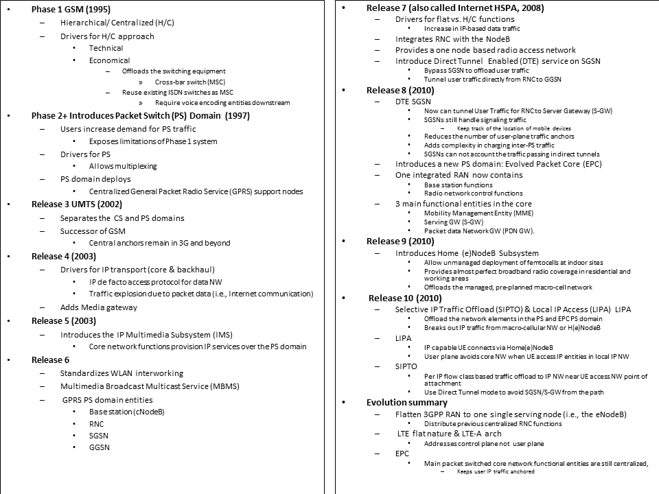
Packet Switch Evolution Table
After a brief discussion of the LTE components, we now focus the rest of the paper on the packet switch entities. This paper concentrates on Flat vs. H/C architectures and their approaches to MM. For space considerations, I’ve synthesized the following table from the text of [Bokor 41]. The table illustrates the evolution of packet switch (PS) NW in mobile communication systems.
Mobile System Scalability Issues
The evolution of mobile communication networks includes the move to Flat architectures. We consider H/C architectures the opposite of Flat architectures. H/C system solutions use central controllers (CC) and base stations (BS). H/C split access-specific functionality over multiple network elements; for example, the CC must operate in unison with BS. The dialog between the CC and BS requires a new NW protocol, and introduces the typical NW headaches (loss, latency, jitter). In addition, engineers must define, maintain & test the interfaces (I/F) before deployment. The CC and BS require failure recovery for lost, duplicated, delayed, proprietary messages, which adds complexity to the system in the form of redundant I/F, longer transmission times, higher development costs and higher OPEX. We can flatten the H/C system and remove the specialized backhaul protocol, and replace the protocol with a simple IP-based network. [Bosch 3865]
H/C approaches cause control plane scalability issues. Separate service and access layers introduce additional complexity for session establishment procedures. For interaction between these layers during session establishment, the system requires special schemes, such as the policy and charging control (PCC) we discuss in the IP Multimedia Subsystem (IMS) section below. PCC must ensure the bearer on the access network matches service layer resources and operator policy and user subscription permissions. A large number of standardized interfaces mean the service & access layer balancing could cause issues in the control plane. The control plane suffers scalability and QoS issues. [Bokor 45]
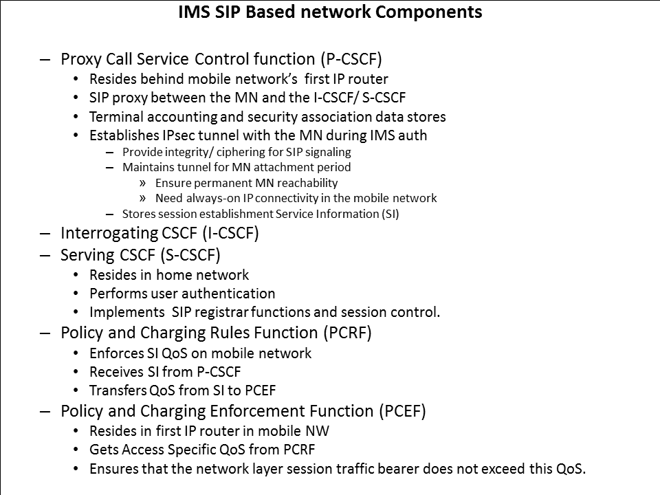
Let us look at IMS in detail, and how the Session Initiation Protocol (SIP) approach to signaling may lead to bottlenecks. 3GPP defines IP Multimedia Subsystem (IMS) as a service framework that enables fixed and mobile network operators to provide the adequate QoS for transported services and perform a service based differentiated charging. [Daoud 794]. I’ve created the following table that states the various IMS components, based on the text of [Daoud 794]
Doaud emphasizes that IMS and PCC architectures maintain contexts in such a way that increases scalability risks. When we integrate the PCC architecture with SAE the mobility protocol between the P-GW and the access gateways (e.g. PMIP) does not act as a bearer establishment protocol. The MM protocol requires new interfaces. 3GPP adds Interfaces between the PCRF and these gateways, and more interfaces (or more complexity in any form) increase scalability risks, as we will discuss later in this paper. [Daoud 795]. Put succinctly, Daoud writes “IMS, the service control layer on top of fixed and mobile networks, is also centralized and is subject to scalability issues” which correlate to the location of the first IP router seen by the Mobile Node (MN) and the “Number of user related contexts each IMS and mobile network node maintains [Daoud 793].”
In addition to inter-entity, inter-layer protocols, key single nodes-in-the-loop prevent scalability. Anchor points illustrate the concept of key single nodes in mobile system. Anchor points play a major role in both Flat and H/C architectures, in terms of Mobility Management (MM). For anchor points, 3GPP UMTS uses GGSN, SAE uses P-GW and WiMAX uses CSN. Anchor points allocate IP addresses and establish tunnels. For each IP address and tunnel, the Anchor Points maintain “contexts” that contain binding ID, tunnel ID and QoS information. The anchor points update contexts and use them to filter and route user traffic to and from end terminals. Network elements (incl. anchor points) maintain finite simultaneous active contexts. To increase the number of maintained simultaneous active contexts, operators must install new equipment or upgrade old equipment with more capacity. [Bokor 45]. Mobile network engineers investigate MM alternatives to anchor points that maintain contexts, in order to prevent CAPEX. The H/C approach to Anchor Points, and at a higher level, MM requires a single upstream node to maintain state of nodes within their responsibility. The state and context maintenance leads to bottlenecks, since any single entity has finite physical resources. We describe a H/C architecture in the context of GPRS. The RNC, the intelligent part of UTRAN, performs data ciphering, data compression and radio resource allocation. The GPRS SGSN performs user authentication, stores ciphering keys for each user and forwards data to the MN In Accordance With (IAW) bearer establishment routing & Quality of Service (QoS) info. The number of users and/or traffic rate, therefore, impacts the SGSN that maintains a per-user context and lies on the forwarding data path. 3GPP reduces this scalability issue through Direct Tunnel Encryption (DTE). With DTE, data on the forwarding plane does not need to pass through the SGSN. DTE directly tunnels data from the GGSN to the RNC. [Daoud 793].
Single nodes with critical functions for the mobile system become potential bottlenecks. The key nodes either maintain contexts or lie on the data path, which makes them potential bottlenecks. The authors do not favor the H/C approach. Bokor writes "mobile architectures under standardization (e.g., 3GPP, 3GPP2, WiMAX Forum) follow a centralized approach which cannot scale well to the changing traffic conditions" [Bokor 38]. Dauod writes "Due to their centralized design, current mobile network architectures as well as IMS layer will not be able to handle the increasing number of mobile users consuming high bitrate services" [Daoud 793]. Bokor writes of the issues facing LTE, which takes a “flatter” approach than older generations. The eNodeB allows an almost complete distribution of radio and handover control mechanisms and direct logical interfaces for inter-eNodeB communications. LTE allows temporary traffic forwarding between neighboring eNodeB during handover events, which provides intra-domain mobility. Traffic forwarding and inter-gateway mobility operations, unfortunately, remain centralized thanks to the fact that the complex interactions of the S-GW, PDN-GW, Local Mobility Anchor and Home Agent (HA) maintain and switch a centralized, hierarchical and overlapping system of tunnels towards mobile nodes. Bokor writes that LIPTO & SIPA extension offloads (described in my “Evolution of Packet Switch” table above) cannot completely solve this issue, since mobility management mechanisms in current wireless and mobile networks anchor the user traffic relatively far from users’ location. The system manifests a centralized, un-scalable data plane and a control plane with non-optimal routes, overhead, high end-to-end (E2E) packet delay (even in case of motionless users), centralized context maintenance and single point of failures. [Bokor 43]. Daoud writes , “despite the [Flat Arch] effort, scalability issues are still not entirely solved since these architectures remain centralized [Daoud 793].” Daoud writes “the flattening approach appears to be a solution for the expected scalability risks; however the way it is applied for LTE/ SAE and UMTS (HSPA+) does not solve all scalability issues. Even if these architectures remove some of the intermediate nodes, the first IP router is still centralized and manages a high number of users [Daoud 794].”
Reasons for Hierarchical and Centralized (H/C) Approach
H/C approaches contain complex inter-entity communications and protocols, as well as potential single node bottlenecks. Why do we have H/C architectures? Economic factors initially drove the development of the H/C architecture. Systems required expensive, dedicated hardware to vocode and compress voice transmissions. System architects placed these devices in central locations, to share the expense over a large number of users. The compression allowed engineers to send fewer bits over the backhaul connecting the core network to the base. Second to the economics factor, H/C provided redundancy. For CDMA systems, hierarchy performs diversity TX and RX. A central anchor prepares downlink data and distributes to a number of base stations via simultaneous TX over the wireless link. The mobile combines info from multiple legs, and decodes the redundant info that combats fast fading radio channels. On the uplink, the central controller (e.g. UMTS RNC) selects best voice uplink packet before TX the received packets to vocoders. [Bosch 3864]. In spite of this, we will discuss how “the economic reasons for designing cellular systems in a hierarchical manner have disappeared: in fact, hierarchical architectures hinder future efficient deployments [Bosch 3864].”
Conclusion
Next Month we will continue the investigation and discuss Flat Architectures and evolved mobility management (MM) approaches.
Bibliography
- Ali, Ifran, Alessio Casati, Kuntal Chowdhury, Katsutoshi Nishida, Eric Parsons, Stefan Schmid and Rahul Vaidya. “LTE 3GPP RELEASE 8: Network-Based Mobility Management in the Evolved 3GPP Core Network.” IEEE Communications Magazine February 2009: 58-66
- Bogineni, Kalyani, Reiner Ludwig, Preben Mogensen and Vish Nandlall. “LTE Core: Part I.” IEEE Communications Magazine February 2009: 40-43
- Bokor, László, Zoltán Faigl and Sándor Imre. “Flat Architectures: Towards Scalable Future Internet Mobility.” Future Internet Assembly LNCS 6656 2011: 35–50
- Bosch, Peter, Louis Samuel, Sape Mullender, Paul Polakos and Gee Rittenhouse. “Flat Cellular (UMTS) Networks.” IEEE Wireless Communications & Networking Conference (WCNC) 2007: 3864-3869
- Daoud, Khadija, Philippe Herbelin and Karine Guillouard. “Performance and Implementation of UFA: a SIP- based Ultra Flat Mobile Network Architecture.” PIMRC 2009: 793-797
- Sarin, Arun. “The Future Of Convergence In The Communications Industry.” IEEE Communications Magazine September 2007: 12-14